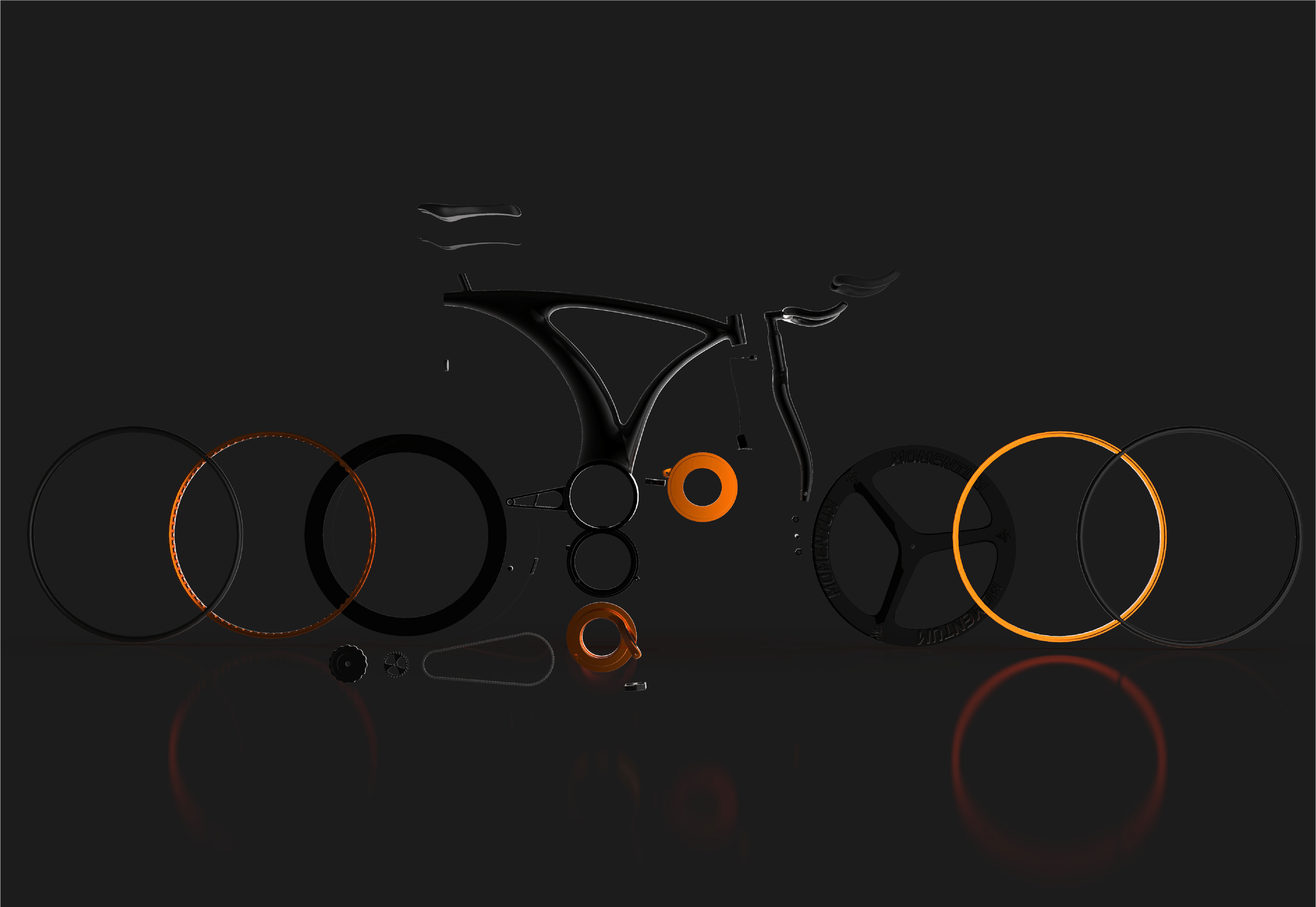
Momentium
A new break system and wheel connection system.
June 2020
Design, 3D modelling and Rendering.
Background
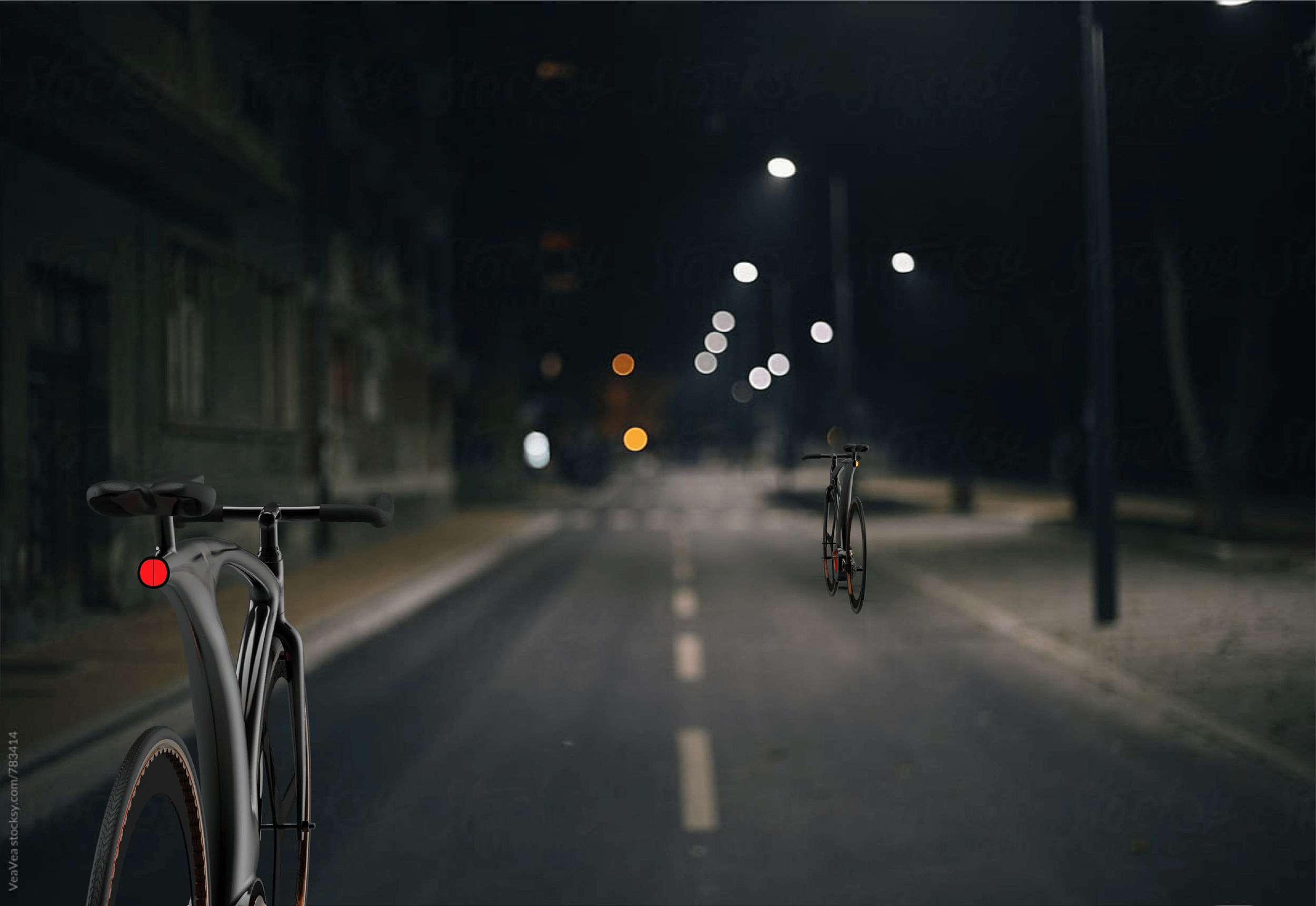
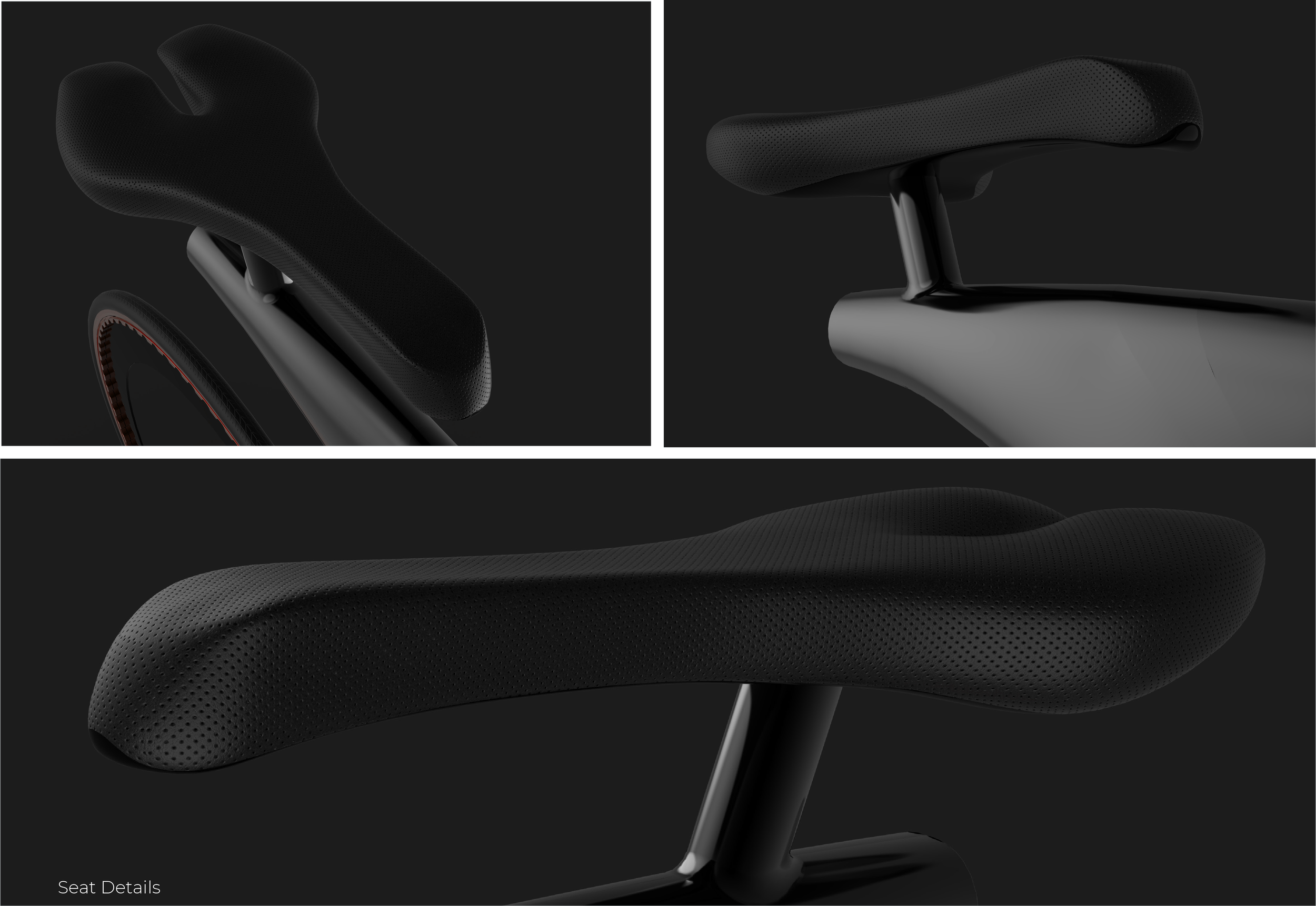
My design has been driven by my primary focus on aesthetics and simplicity of riding and then iterating through the various constraints to a point to ensure form meets function.
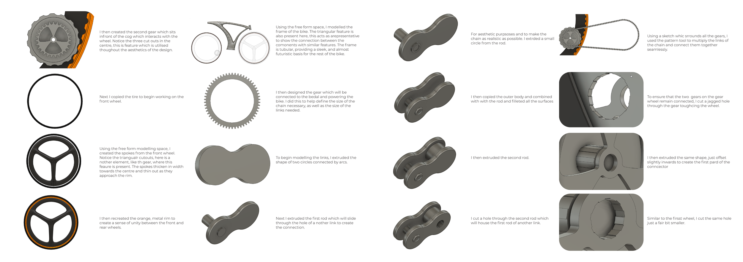
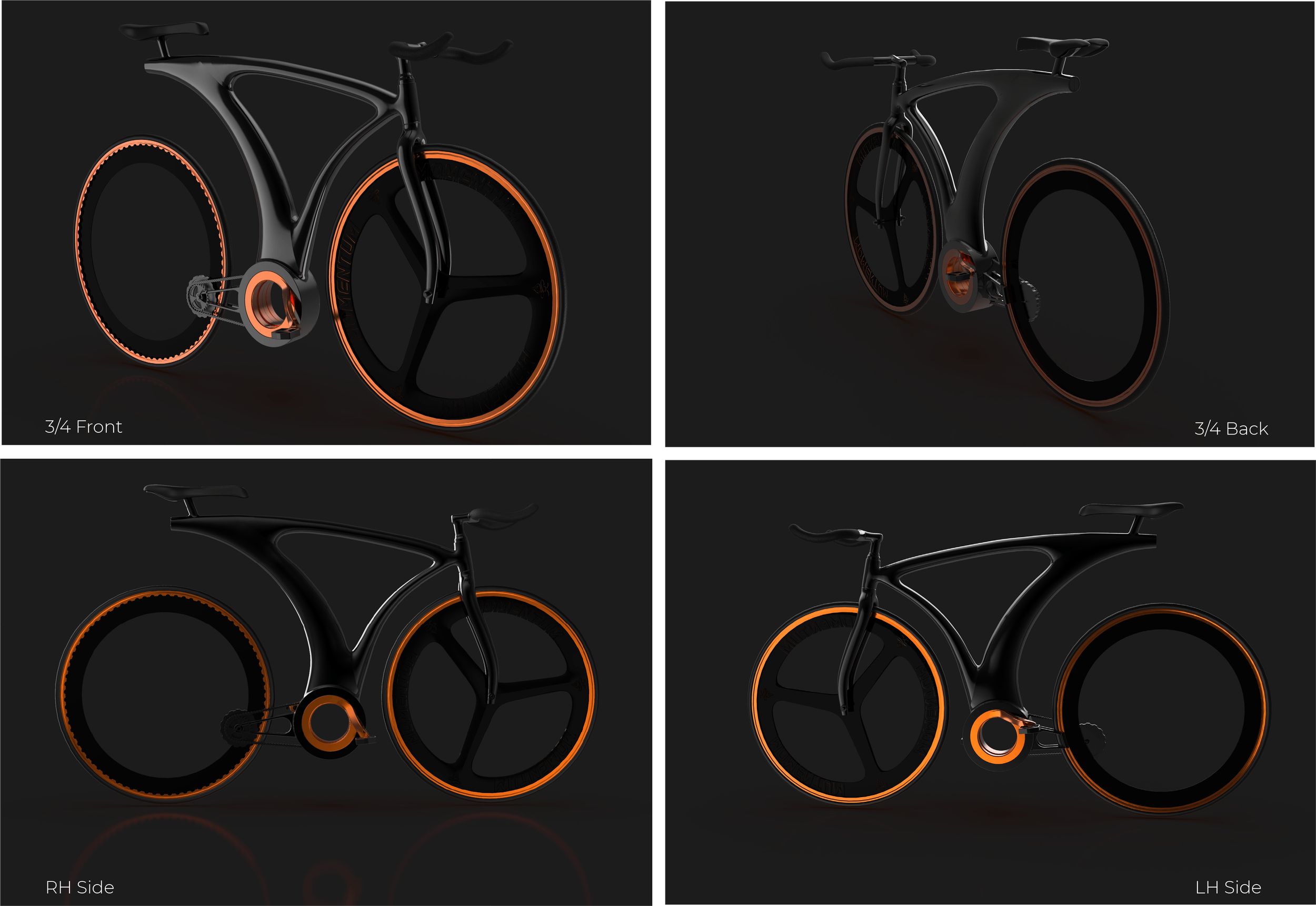
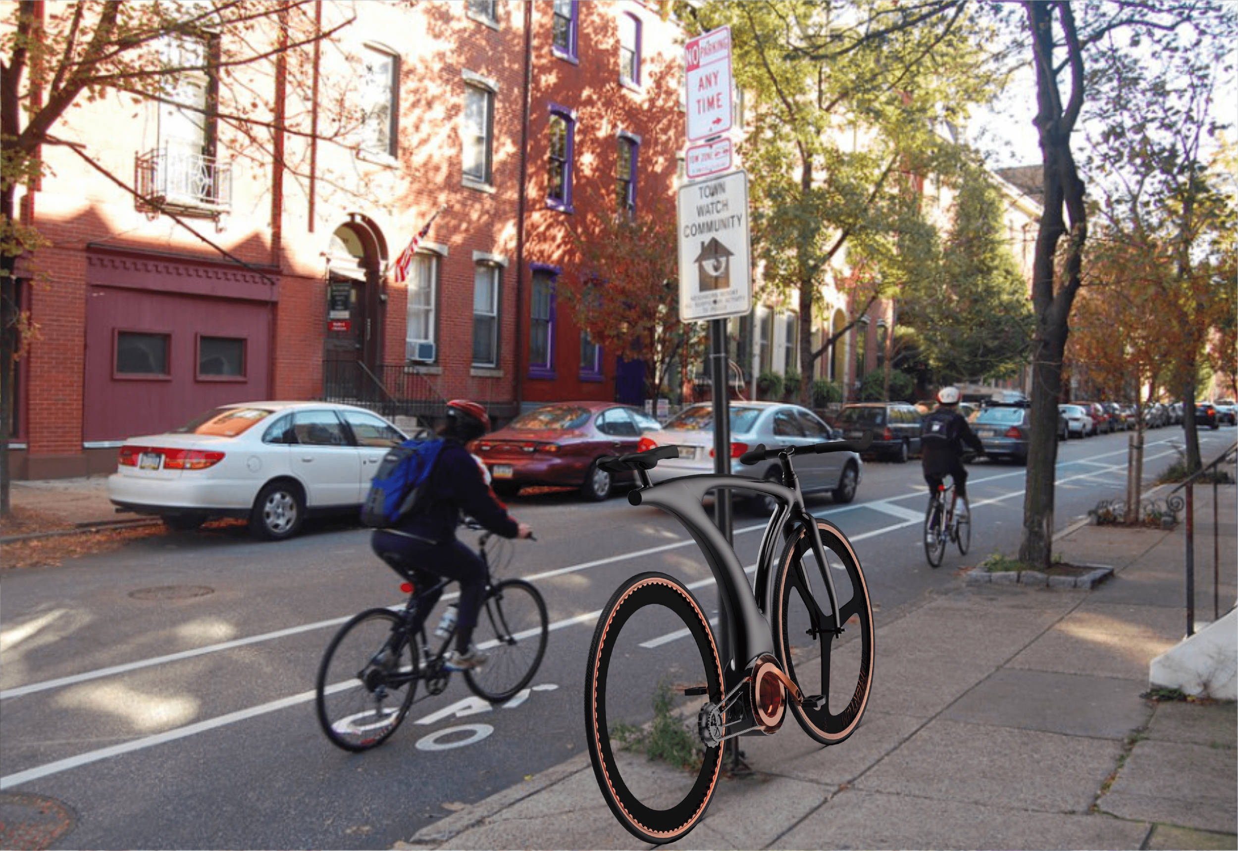
With the occasional, neighbourhood, cyclist in mind, I have decided to focus on fixed gear (‘fixie’) bike designs. It ensures a simple, easier ride as one is not focused on gear shifting and eliminating many of the issues due to their complexities. A ‘fixie’ also eliminates the need for a back wheel brake – improving on looks (see later).
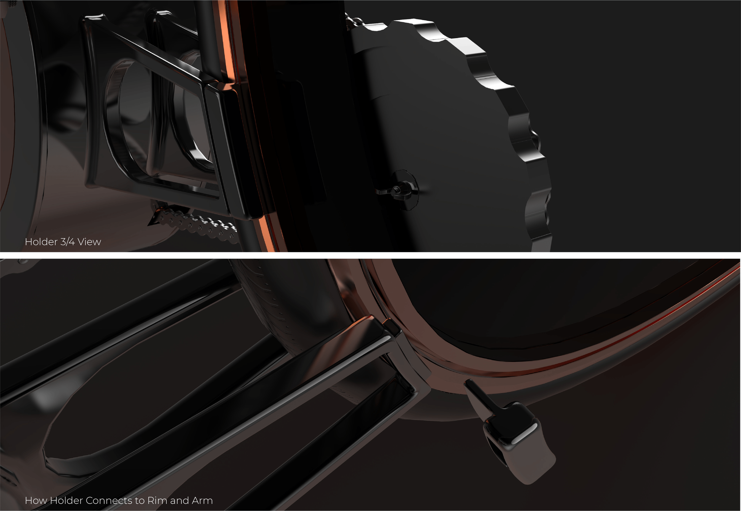
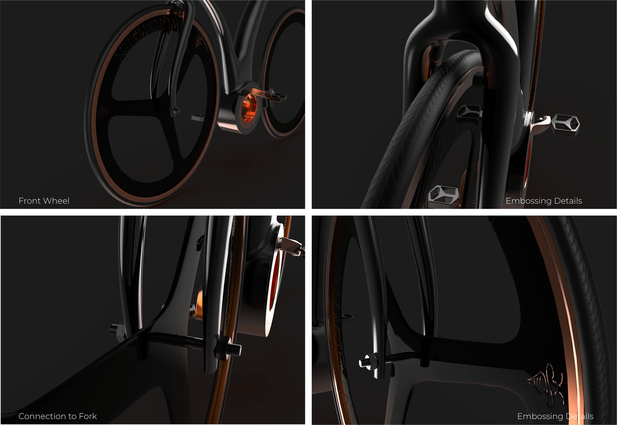
I decided to incorporate a hub-less wheel into my design – as it looks cool. While hub-less requires greater manufacturing precision – the removal of the cost and complexities of multi-speed gears is likely to more than counterbalance the precision manufacturing costs. There are potential benefits with hub-less -e.g. reduced weight, air resistance and so on (better handling, steering, etc), however, as this is a neighbourhood bike these do not play any significant role and possible deficiencies brought about by precision are also not of great importance on standard roads.
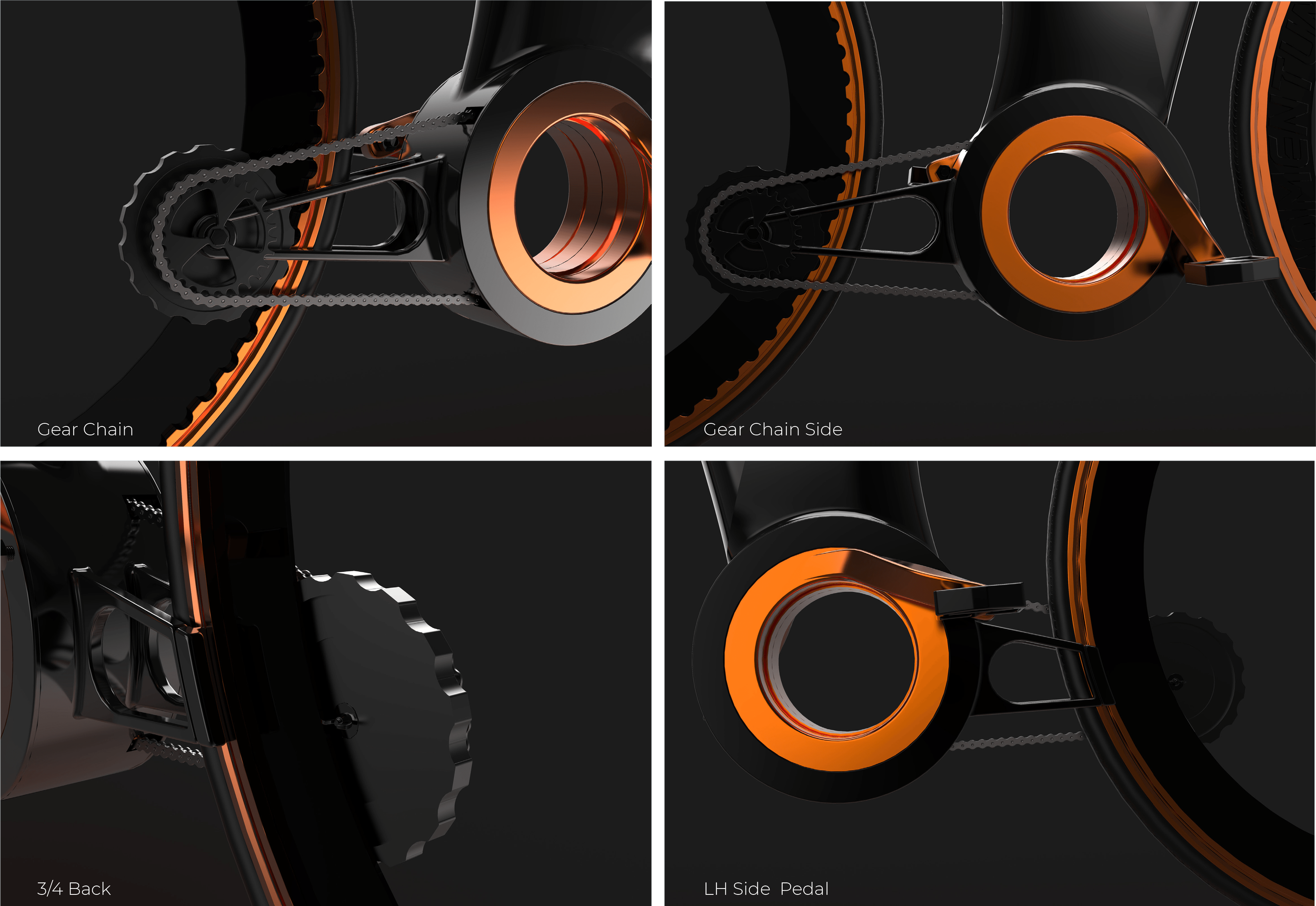
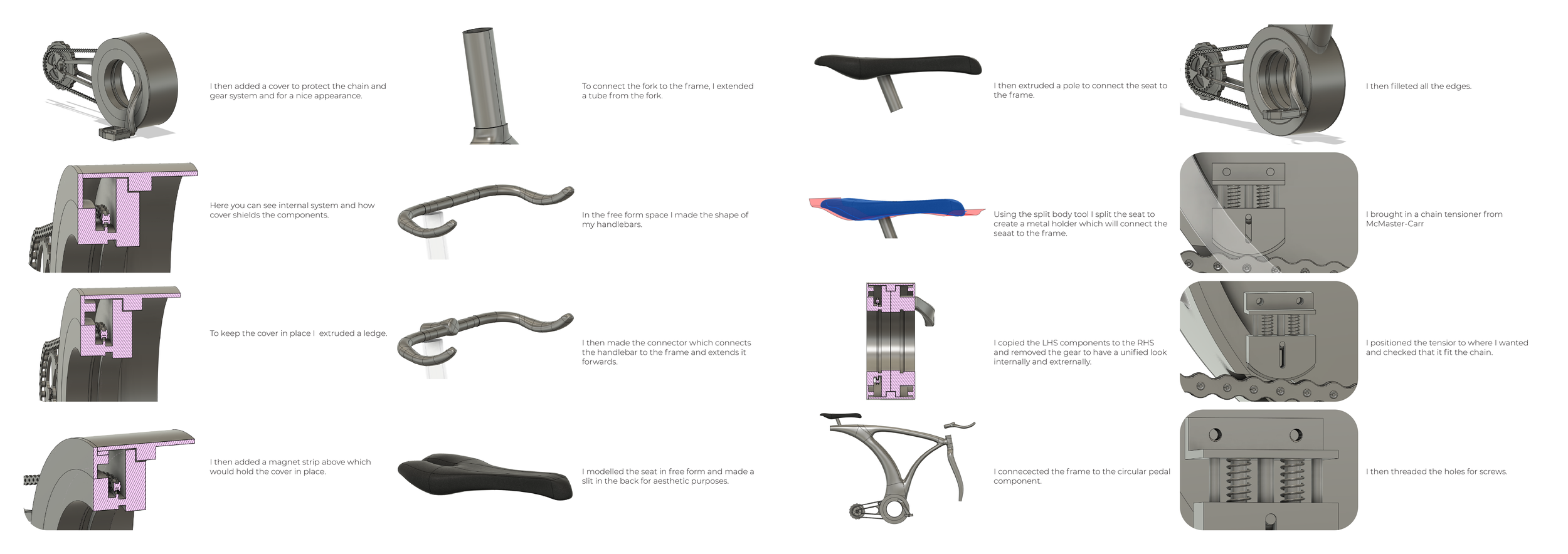
One of my earlier iterations involved a transmission gearing (multiple) from the pedals to a hub-less wheel, however, I decided that the complexity of maintenance, cost of multiple-precision parts, power losses, and so on had significant downside to any possible aesthetic benefits. Given the distance to the mechanism on the wheel, I decided that a better approach would be using a standard chain, however, hiding various items such as the peddle cog wheel, chain tension, etc.
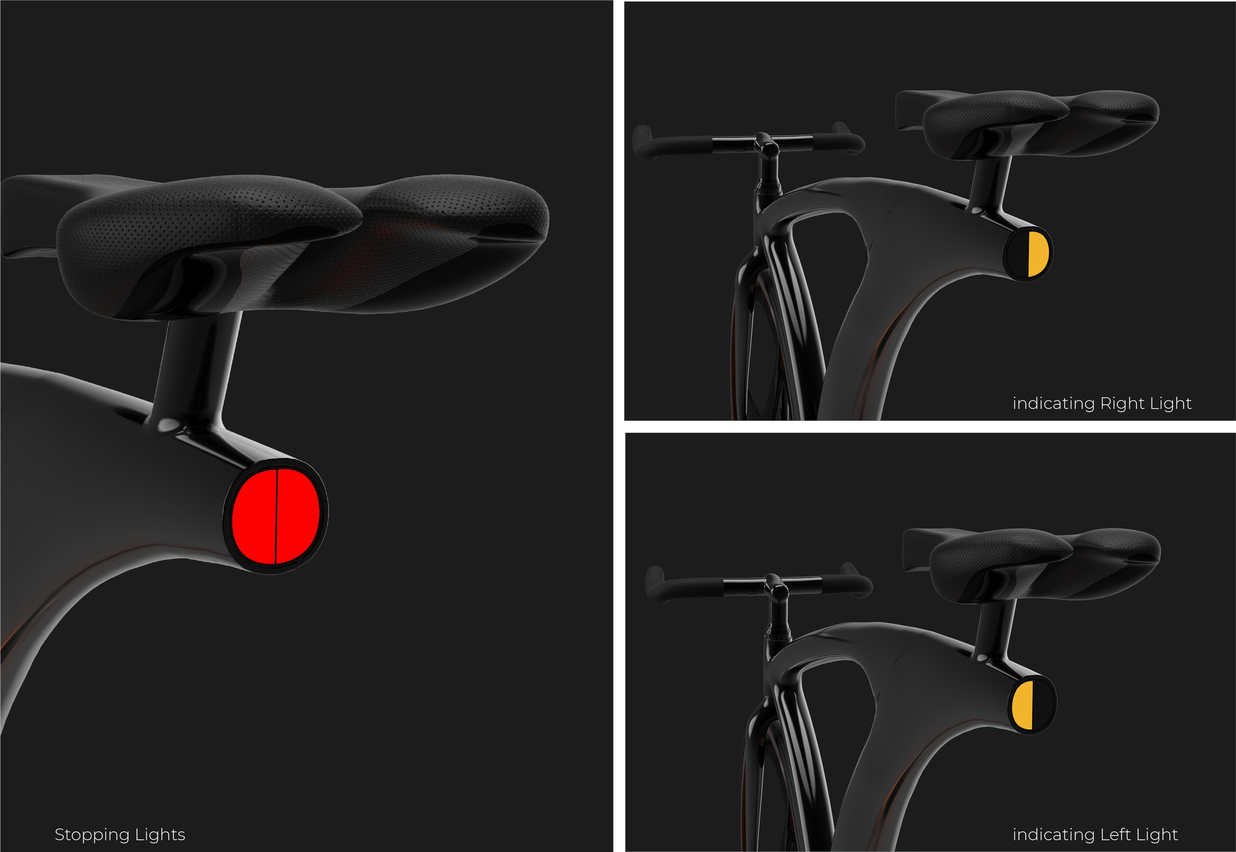
I found that the standards approach brake systems looking like afterthoughts – clumsy add-ons with wires – that do not match the aesthetics of the bike. I spend a considerable amount of time trying to reimagine them – in the end, I have designed a novel solution that incorporates it into the frame – hidden from view. By having a ‘fixie’ I eliminated the need for a back-wheel break – which improved aesthetics and did away with the need to have two different breaking solutions.
Features
Brake system
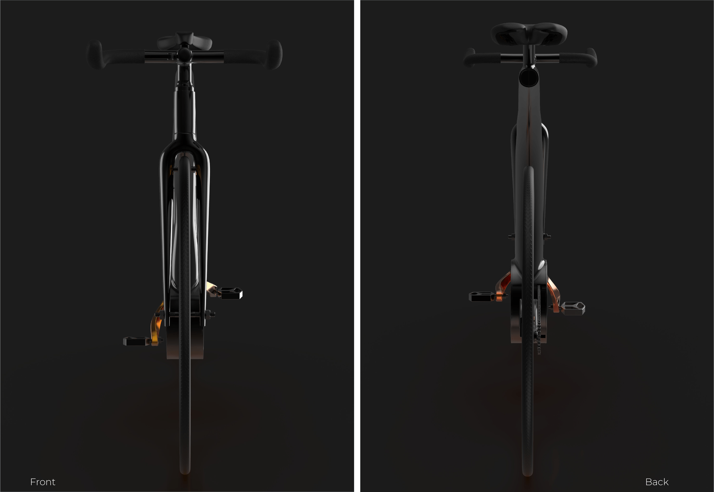
The bicycle is designed with a fixed-gear (ratio), which is commonly referred to as a ‘fixie’ (alternatively – ‘single-speed’ or ‘fixed-speed’). The operation of the breaking subsystem in a ‘fixie’ differs from a multi-speed bicycle – requiring no breaking subsystem for the back wheel, rather, breaking is inherent in its design. With the virtually instantaneous breaking of the back wheel, it is the job of the front wheel braking subsystem to provide the variable and more controlled slowing down of the bicycle.
Typically, breaking subsystems are large, and appear as almost an afterthought ‘add-on’ with their wires and attachments around the wheels (or the spoke, in disk brakes) – spoiling the ‘look’ of the bicycle. I did not wish to replicate the standard approaches in my bicycle design. I decided to incorporate the entire braking subsystem into the frame of the bicycle, necessitating a new and novel approach to overcoming issues such as size due to the limited depth of the frame, assembly and complexity as it needs to go into the frame and so on.
Front Wheel Configuration
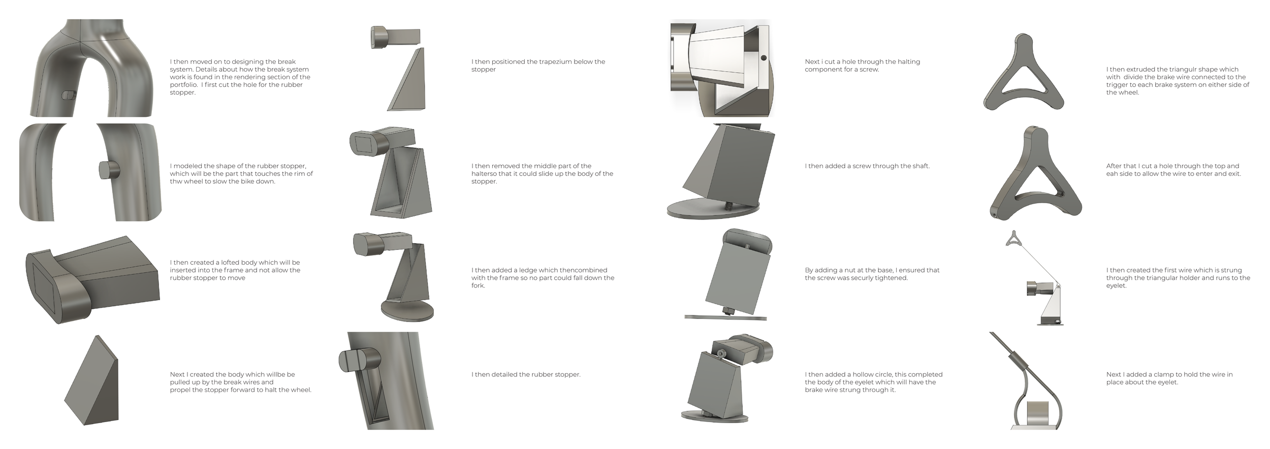
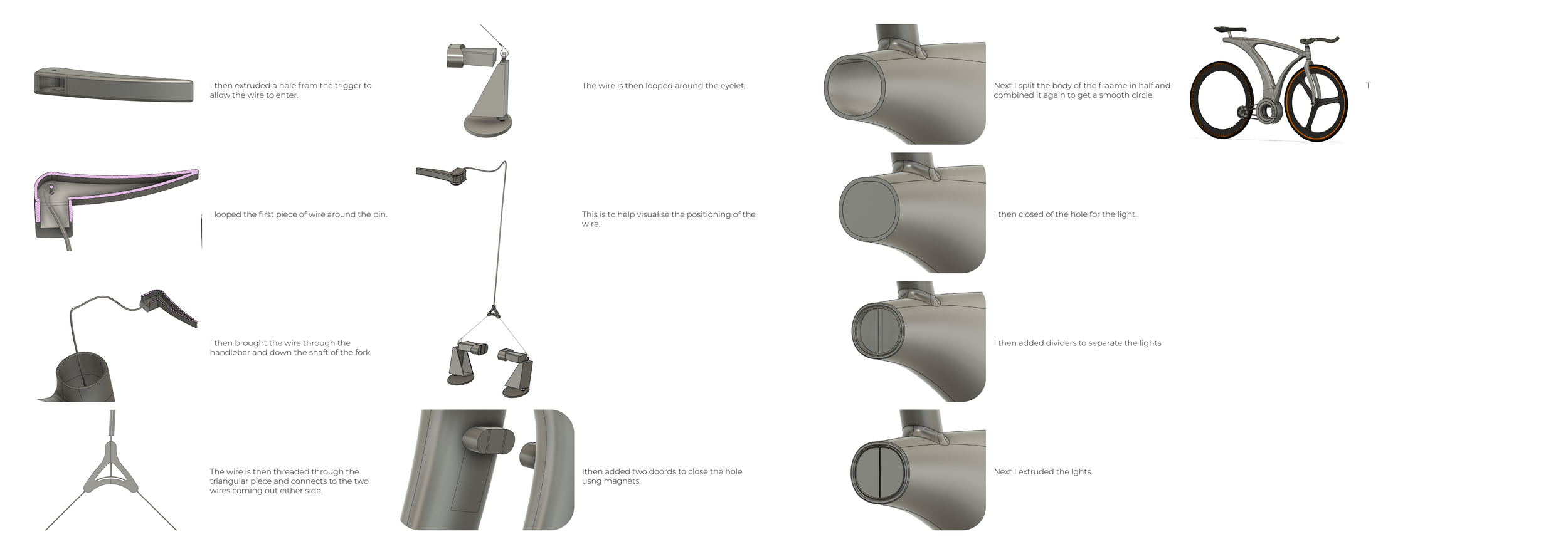
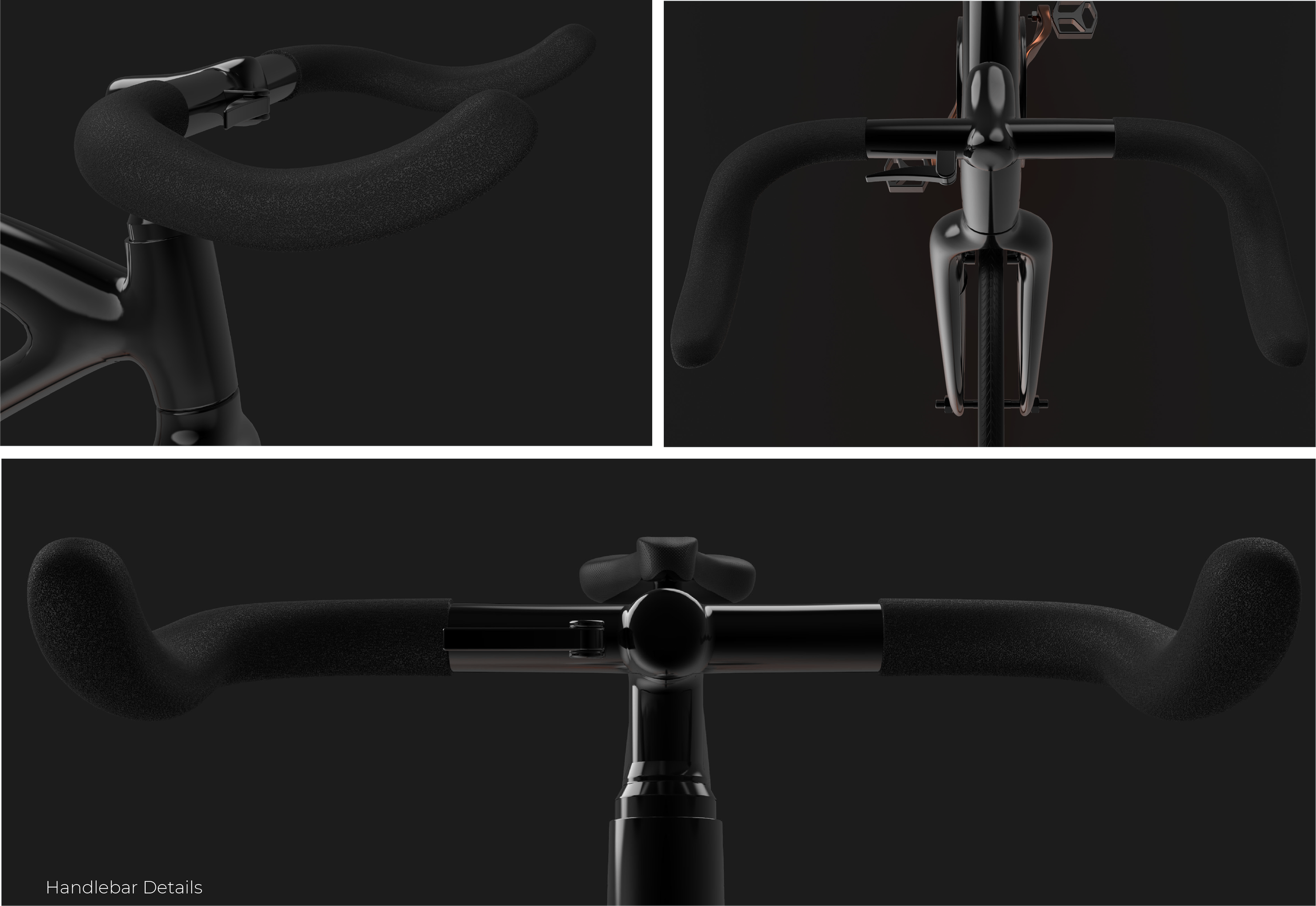
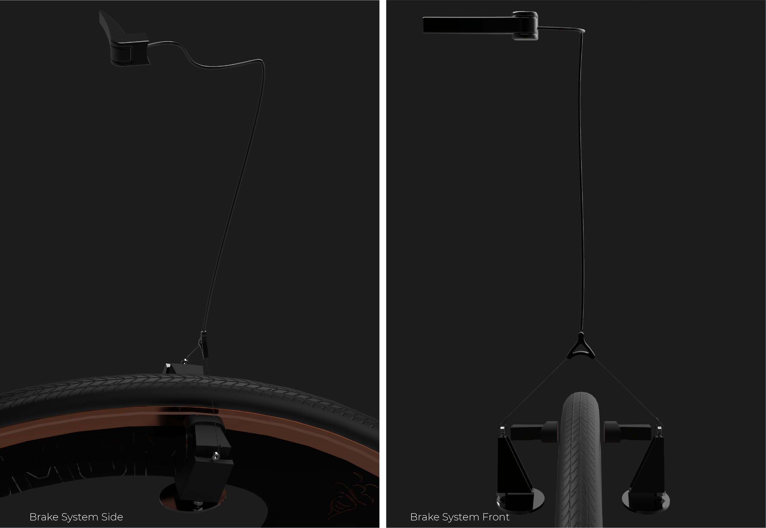
The front-wheel braking subsystem if incorporated into the frame. Breaking is, ultimately, achieved via equal pressure being applied to either side of the front wheel using brake pads which slow down the wheel via friction. The cyclist controls the amount of pressure applied to the wheel by pulling on a break-lever which forms part of the handlebars – a standard approach where the lever movement pulls a breaking wire (incorporated into the frame) – ultimately leading to the break-pads moving towards and pressing the wheel. The break-lever wire runs into the inner part of the frame and through it - first via the handlebar and then via the ‘head tube’ which lies between the handlebar and the rest of the frame - to the fork in the frame which holds the front wheel on either side.
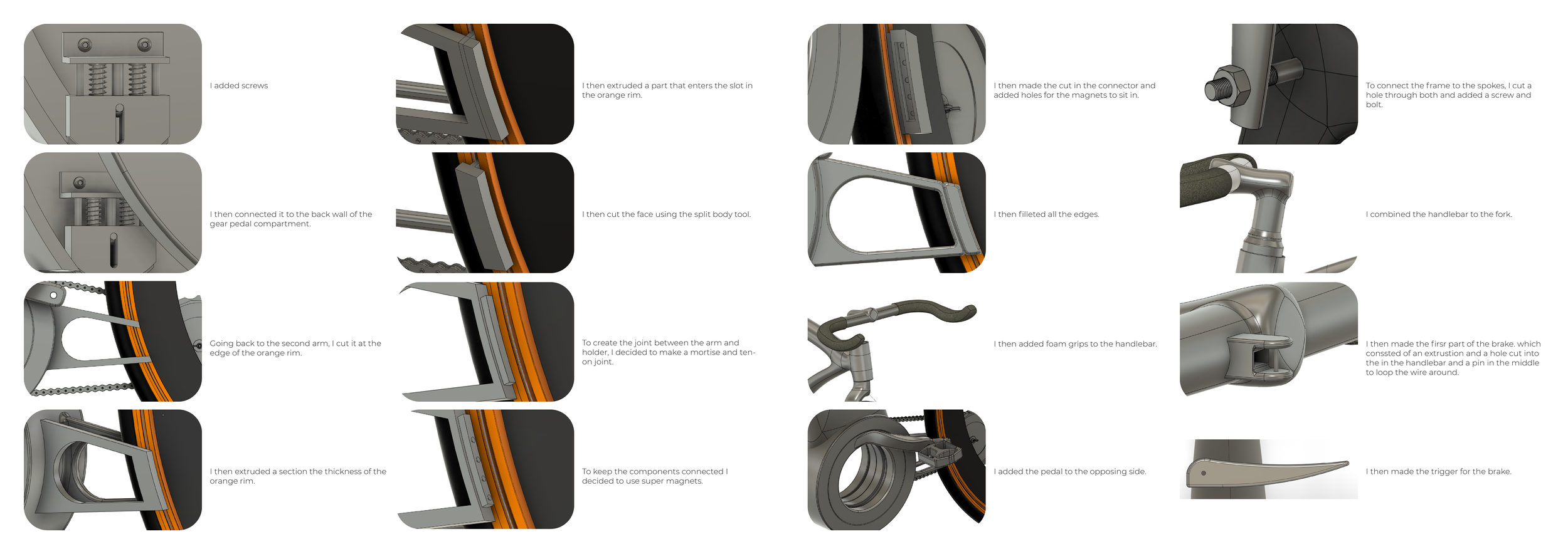
The single wire and the ‘pulling up’ action due to the brake lever being squeezed is ‘transferred’, via a Y-type Junction, to two separate wires, of equal length running inside the two sides of the fork which holds the front wheel. At the end of each wire, there is a free-moving (vertical) ’90 degrees triangular-shaped construction (‘triangle’) – i.e. the pulling of the brake lever results in this ‘triangle’ moving upwards. The longest side of the ‘triangle’ (hypotenuse) is facing the wheel. It is made from very low friction material and weighted to ensure it always returns back to its original position once the break-wire upwards movement/tension is released (break-lever back to original state). The longer side of the triangle is ‘keyed’ (channels). These channels are used to ensure that the brake pads operate in unison with the movement of the ‘triangle’ and restrict side movements.
The brake pads are positioned in line with the top of the triangle and parallel to its base and are composed of an internal part (inside the frame) and an external, larger, part which is exposed outside of the frame (‘mushroom-like construction which restricts the movement so the exposed part cannot ‘fall’ into the frame). The internal part incorporates a flexible ‘wing-like’ design which pushes against the frame (wedge gets wider away from opening) so that brake pads are always pushed as far in as possible and no further than the larger ‘exposed top’ allows (natural position). The internal part engages with the triangle via the channels mentioned above (both surfaces are low friction to allow free movement – ‘triangle’ vertically, and brake pad ‘horizontally’). The exposed part is made of a suitable pad material which provides a suitable degree of friction to act as a brake pad (i.e. high friction, softer material – vs. the low friction, denser material used for the internal part).
When the brake lever is pulled it causes the ‘tringles’ to move upwards. As they move upwards, they reduce the available space for the internal brake-pad part – resulting in it being pushed outwards – horizontal movement – moving the exposed brake pads towards the wheel – ultimately engaging it and slowing it down via friction. The release of tension results in the ‘triangles’ dropping down and the spring mechanism built into the brake pads to pull it back towards its initial position – away from the wheels and (only) a small exposed element. Using this novel design, I have managed to largely incorporate the brake pad into a narrow frame overcoming the large movement required with the standards approach.
Installation and maintenance
The fork incorporates a T-type slot which allows the pulling of the end of the wire out to easily clip it into the end of the ‘triangle’ The wider part of the slot is used for inserting the brake pad component. The process is to connect the ‘triangle’ with the wire, connect the brake-pad narrow/internal part (i.e. the bottom of ‘mushroom’) to the channel on the triangle and slot the two of them through the respective parts of the T-slot (hole). Restricting the triangle dropping down further is achieved by matching it to the drop in width in the frame but can equally be done by adding a form of constraint in the frame (e.g. tab). The vertical part of the T (longer part) is then sealed with a cover. The horizontal part (the top of the T) is sealed by the ‘exposed’, larger part, of the brake pad – which is pulled inwardly. The design is thus amazingly simple to install and maintain. No special tools. No adjustment. Each part can be replaced based on its Brake System Side Brake System Front own wear and tear – including the exposed pads which suffer greater wear and tear, and which are locked into the other part of the brake pad component.
Back Wheel Configuration & Connection System
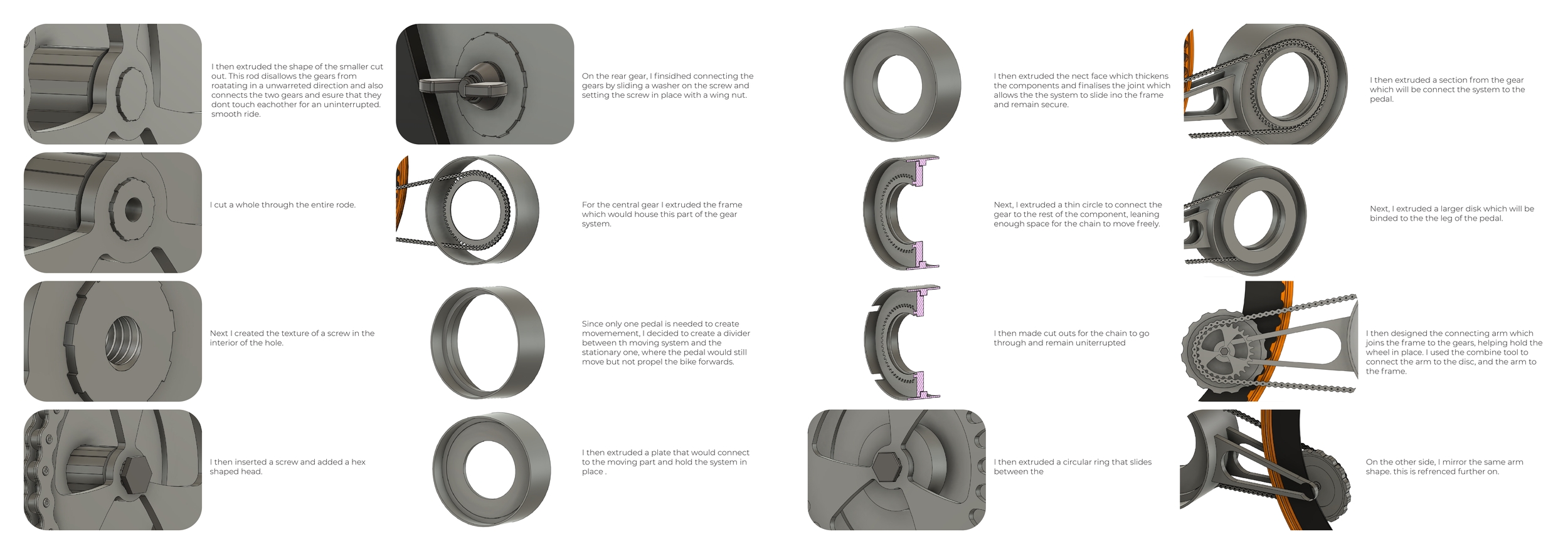
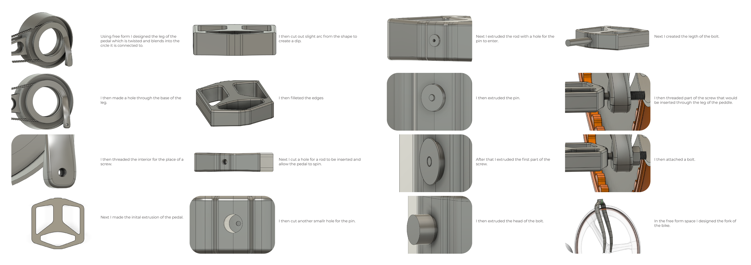
With a single gear and no derailleur (variable-ratio transmission system) as long as the wheel is turned the peddles turn and vice versa. Breaking of the back wheel is achieved by the cyclist putting pressure on the peddles to stop them from turning. This action locks the chain in place which in turn locks the gear which is responsible for rotating the back wheel – thus causing the wheel to lock in place. Thus, there is no need for a brake subsystem to be incorporated into back wheel.